The Valve Wizard |
|
|
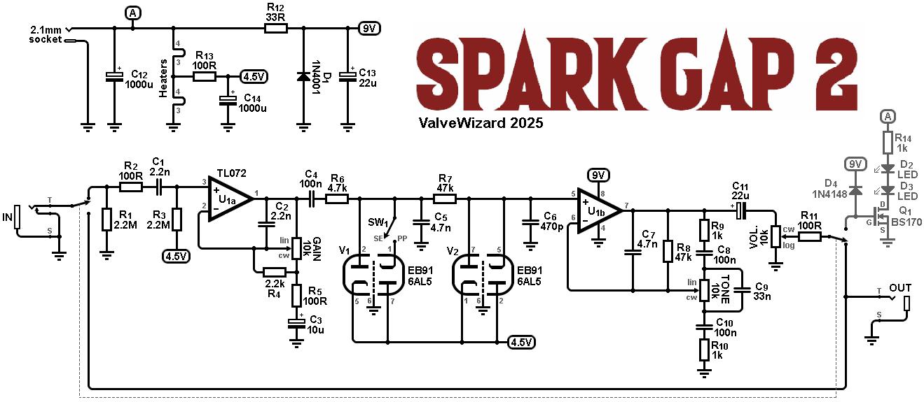
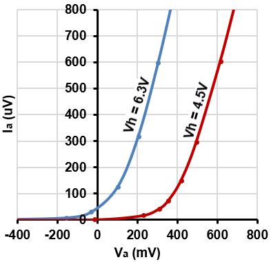
However, some years ago I discovered something interesting about the EB91/6AL5 –a very common and cheap double diode. When its heater voltage is reduced, its whole I/V characteristic shifts to the right, creating a useful diode characteristic for small signals, as illustrated in the graph further down this page. Most other valves do not behave this way, their dynamic resistance simply increases when the heater voltage is reduced, without changing the actual diode threshold voltage. I exploited this property of the EB91 to create a kind of Tube Screamer with real valve diodes, which I called Spark Gap. However, my original design was pretty basic -just a proof of concept- and it could only acheive mild overdrive. Finally I re-visited the idea and present here "Spark Gap 2", the first distortion pedal I am actually proud of. Unlike it's wimpy predecessor it can acheive high levels of creamy to crisp, true-valve overdrive, and a huge tonal palatte, with surprisingly few parts. Best of all, it does not suffer from the 'woolly', flatulent overdrive quality of most other low-voltage tube pedals.
Since the dynamic resistance of the valves is relatively high, two stages of diode clipping are cascaded between the two opamps, so a high level of distortion can be achieved. C5 and C6 provide additional filtering of excessively shrill harmonics. With SW1 closed, both clipping stages are symmetrical, which mimics the symmetrical clipping of a purely push-pull amplifier, and the final result is similar to most diode-clipping pedals on the market. But there is one final trick to be played here. When SW1 is open, the first clipping stage becomes asymmetrical. C4 is now able to charge rapidly through R6+V1 on positive cycles, but it can only discharge more slowly through R6+R7+V2 on negative cycles. This causes the average voltage across V1 to shift negatively during overdrive, which dynamically changes the clipping threshold depending on the signal amplitude. Exactly the same effect occurs in most real valve amplifiers. It causes the overdrive sound to change or ‘swirl’ as the guitar signal sustains and decays, and it allows the player to exploit different tones by varying how hard s/he plays, ‘riding’ the clipping threshold as it were. This is something most commercial distortion pedals do not do, leading them to sound rather monotonous compared to a real amplifier.
Total current consumption is about 260mA, depending on valve heater tolerance. This is relatively high for a pedal, so battery power is out of the question. It is essential to use a good quality, quiet power supply, which is often the price that is paid for using valves, but well worth it in my opinion.
|
 Most guitar overdrive effects rely on diode clipping to generate distortion, and many players like to experiment with different kinds of diode, Zeners, and LEDs.
Some also experiment with valve diodes in an attempt to emulate the sound of an overdriven valve amplifier.
However, at low voltages the results are often disappointing, because a valve diode will normally conduct some forward current even when the voltage across it is zero or slightly negative (this current is driven by the space charge itself).
For very small signals, a valve diode therefore looks more like a resistor than a diode, producing a weak distortion sound at best.
Most guitar overdrive effects rely on diode clipping to generate distortion, and many players like to experiment with different kinds of diode, Zeners, and LEDs.
Some also experiment with valve diodes in an attempt to emulate the sound of an overdriven valve amplifier.
However, at low voltages the results are often disappointing, because a valve diode will normally conduct some forward current even when the voltage across it is zero or slightly negative (this current is driven by the space charge itself).
For very small signals, a valve diode therefore looks more like a resistor than a diode, producing a weak distortion sound at best.